Isentropic Compression Ts Diagram
It is possible to perform a series of processes in which the state is changed during each process but the gas eventually returns to its original state.

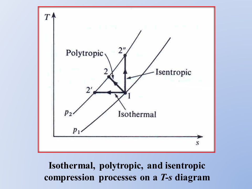
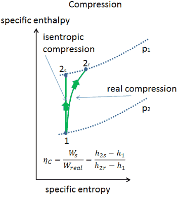
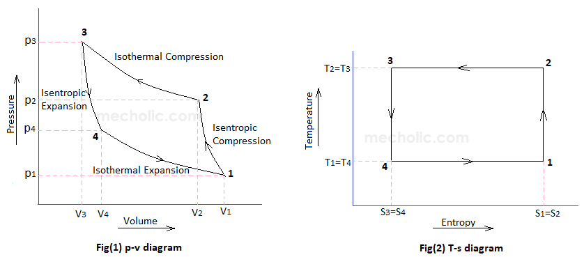
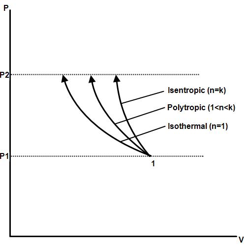
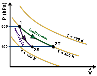
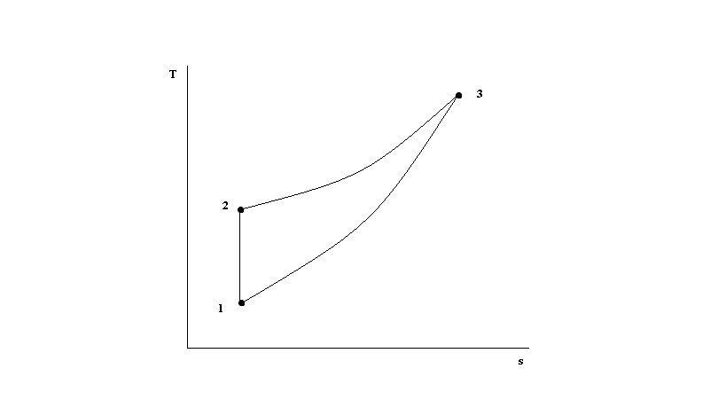
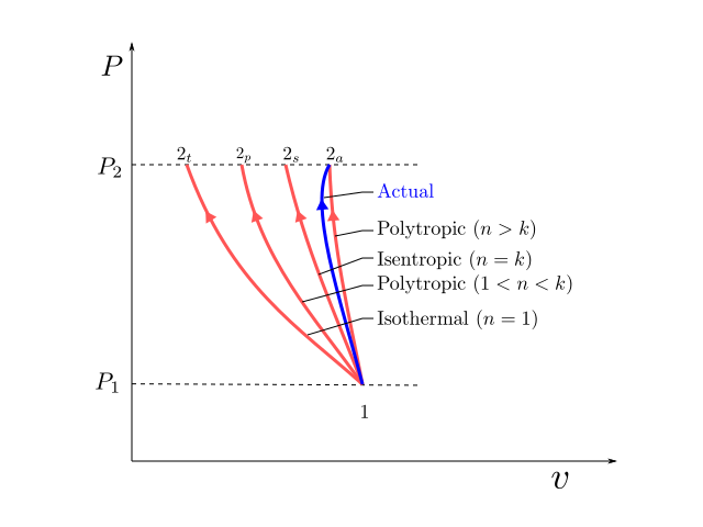
Isentropic compression ts diagram. Hear rejected work done on the air. The parameter that describes how efficiently a device approximates a corresponding isentropic device is called isentropic or adiabatic efficiency. In this diagram the path 2 3 represents the polytropic compression and the path 2 3 represents the isothermal compression and the path 2 3 represents the isentropic compression. From the above diagram it is clear that the air is drawn in by the cylinder during the suction stroke 1 2.
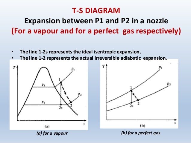
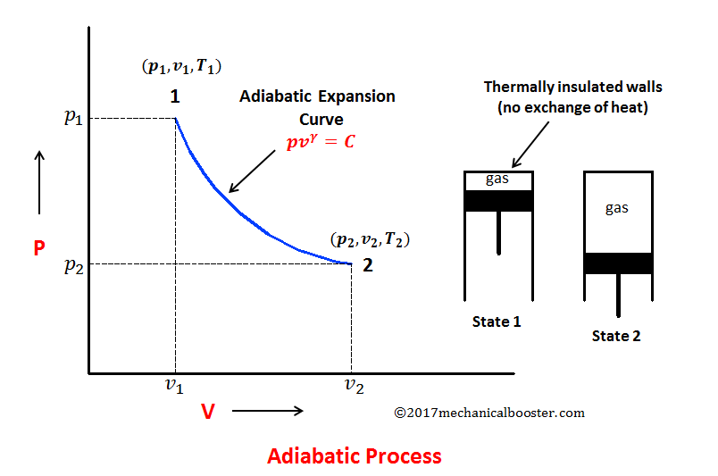
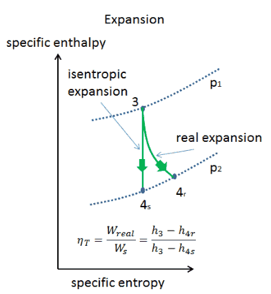
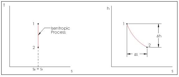
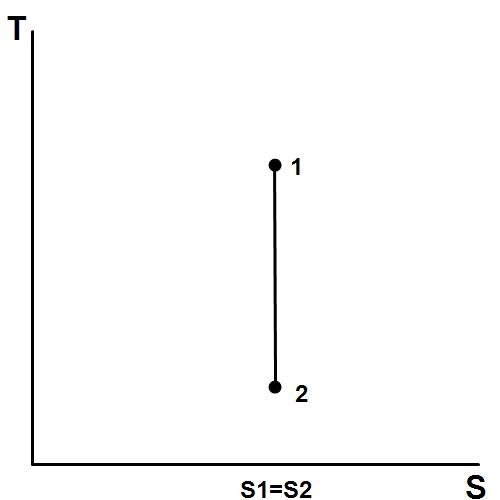
P v diagram of an isentropic expansion of helium 3 4 in a gas turbine. An isentropic process appears as a vertical line on a t s diagram. Well you can see from the ts diagram that some of the excess energy is converted into internal energy resulting in an increase in temperature. Remember that our system contains an ideal gas with constant heat capacities and therefore a constant heat capacity ratio.
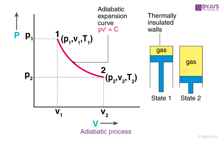
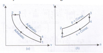
Lets begin by plotting an isentropic process path on both a pv and a ts diagram. P 3 67 mpa. Assume an isentropic expansion of helium 3 4 in a gas turbinesince helium behaves almost as an ideal gas use the ideal gas law to calculate outlet temperature of the gas t 4isin this turbines the high pressure stage receives gas point 3 at the figure. Isentropic expansion in gas turbine p v diagram of an isentropic expansion of helium 3 4 in a gas turbine.
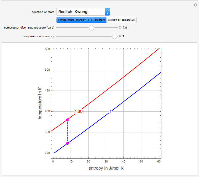
The following figure shows the pv and ts diagram of this compressor. P 3 67. It would be seen that during this process the heat is rejected to the cold body and is equal to the work done on the air. Ch 7 lesson e page 9 isentropic process paths on pv and ts diagrams.
This isothermal compression is represented by the curve 3 4 on p v and t s diagram. Assume an isentropic expansion of helium 3 4 in a gas turbinesince helium behaves almost as an ideal gas use the ideal gas law to calculate outlet temperature of the gas t 4isin this turbines the high pressure stage receives gas point 3 at the figure. Most steady flow devices operate under adiabatic conditions and the ideal process for these devices is the isentropic process. The compression process may be isentropic polytropic or isothermal let p 1 suction pressure pressure before compression v 1 suction volume t 1 suction temperature p 2 v 2 t 2 are the corresponding pressure volume and temperature after compression.
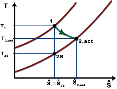
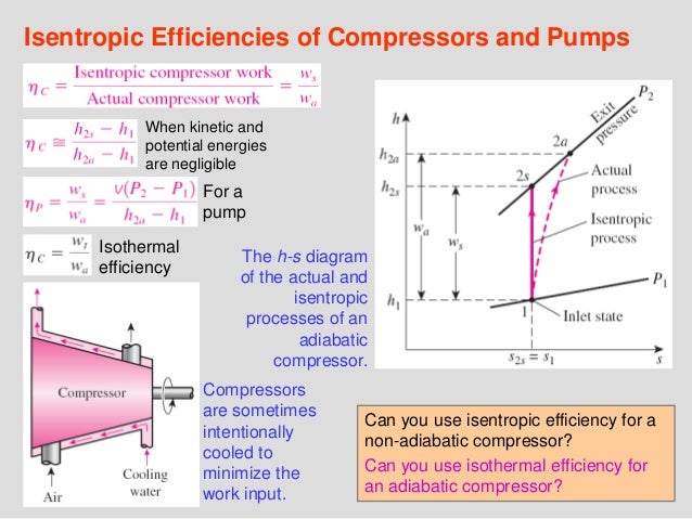
Isentropic efficiencies of steady flow devices in thermodynamic systems. As the temperature increases from t 2s to t 2act along the 05 mpa isobar the specific volume must increase right. Therefore pv 2 is greater for the actual compressor than for the isentropic. Initially this page shows a pv diagram.
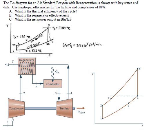
The area under a process curve on a t s diagram is related to the amount of heat transferred to the gas. T 3 1190 k 9170c from a heat.

Isentropic Compression An Overview Sciencedirect Topics
Overview On Thermodynamic Processes With Review Problem English

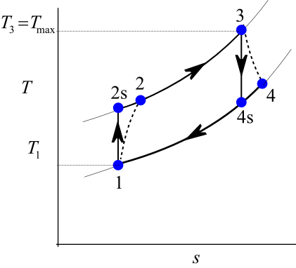
T S Diagram Of An Non Isentropic Compression And Expansion

Thermodynamic Cycles Overview Flashcards Quizlet
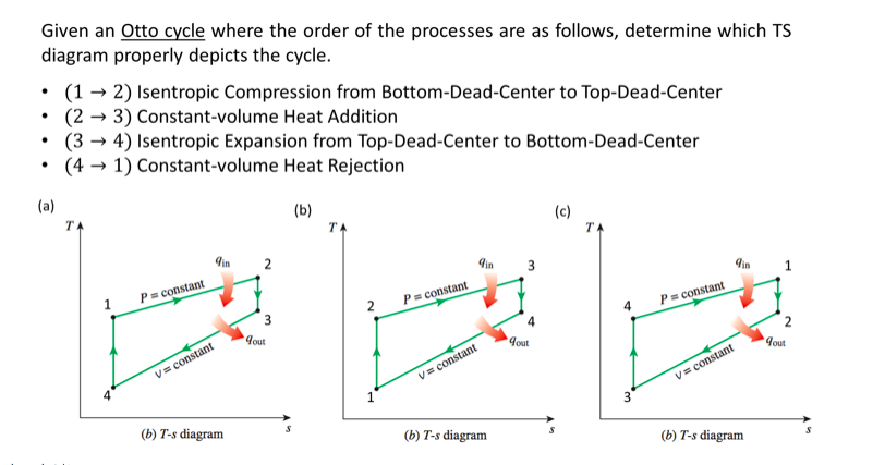
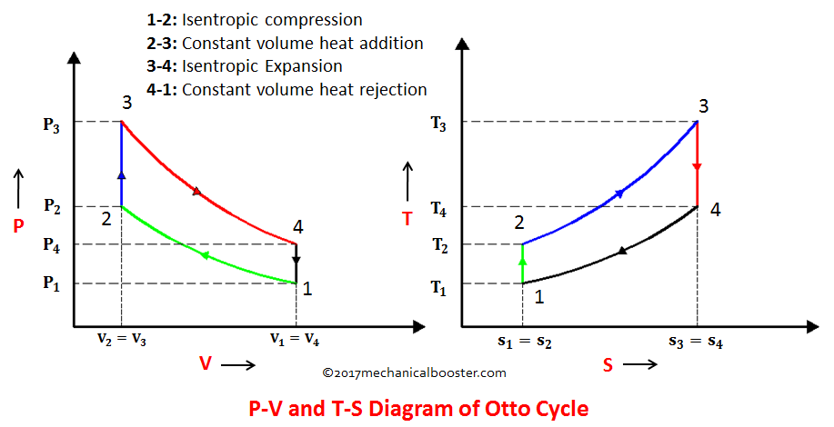
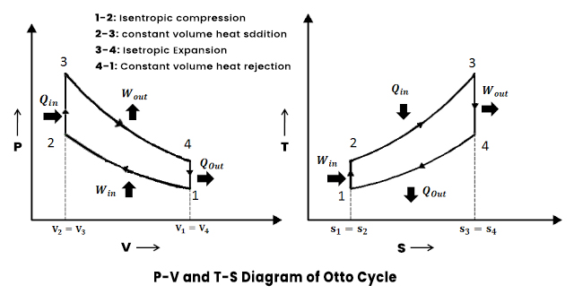
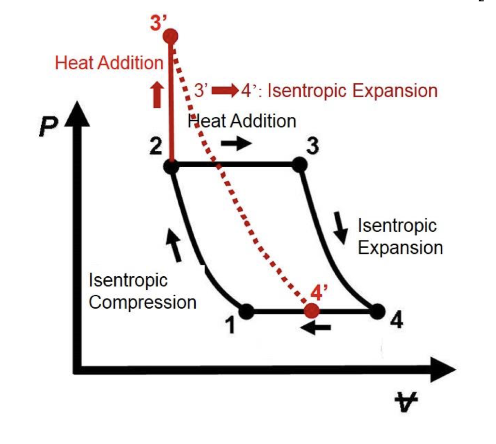
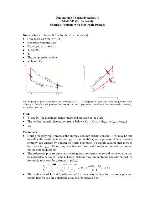
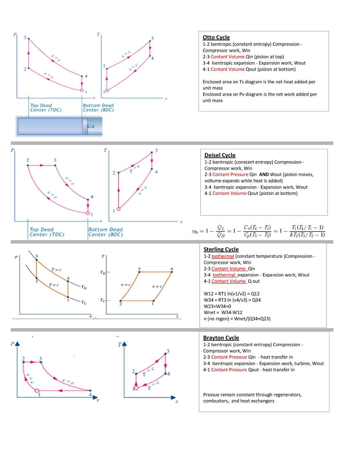
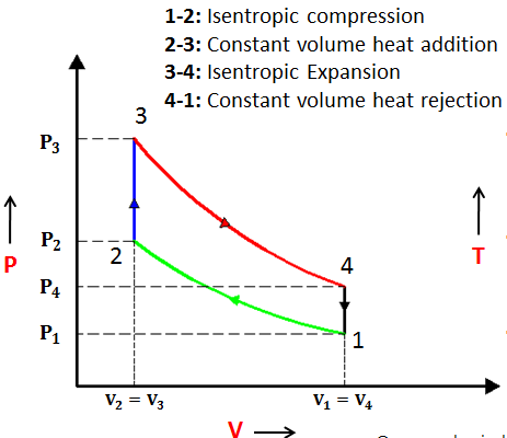
P V And T S Diagram Of An Ideal Otto Cycle Process 1 2 Isentropic